Tabs are the tiny connections between cutout shapes and the surrounding material that helps to hold the shape as it is cut. They are typically small, which means that the shape is able to be broken or cut from the sheet material when the toolpath has been completed. To hold the piece in place the tabs of three or more are commonly employed. To include new entities on an existing toolpath, or build a toolpath from new entities and the tool path could be generated by referencing the currently selected. While QCAD/CAM is specifically designed for producing CAM-specific outputs for use on CNC machines and can be configured to create almost any output from any CAD file. Get More Softwares From Getintopc
Password 123
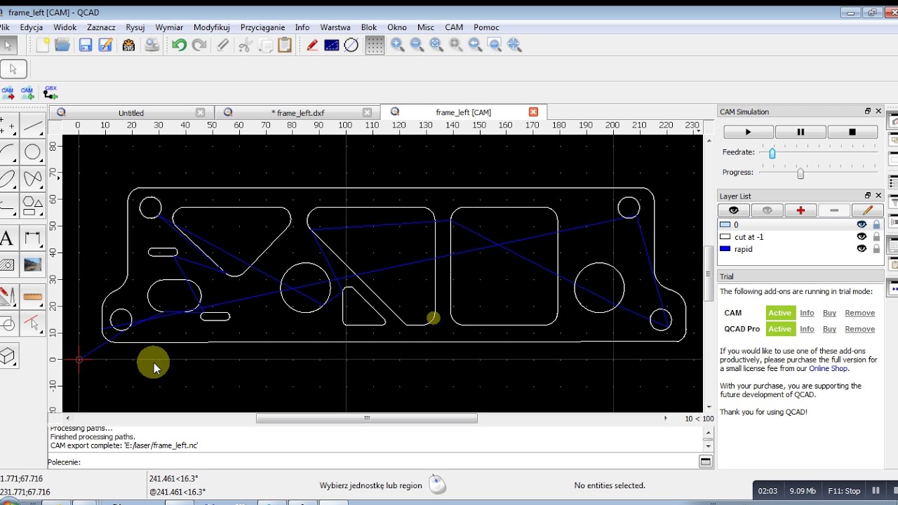
Qcad Cam
One example configuration setting to output G-Code Millimeters is listed in the GCodeMM.js. GCodeMM.js and accessible in the user interface under G-Code (G41/G42). This function alters how visible the layer is CAM, which is the layer where all the path paths are created. If G-code is generated the toolpaths are processed according to the order that is shown. This option is available when there are no G41/G42 commands available or G41/G42 cannot be employed. QCAD/CAM computes the path of the center using the tool radius automatically in this situation and outputs the correct offset coordinates. MyGCode.just create a class named MyGCode in order to function as a valid configuration to QCAD/CAM.
Qcad Cam Features
This code is designed for computer-savvy developers. It is possible to set the output format defined in the following code or later after the output file is created in the very first instance. It is important to be cautious when working with machinery that is hazardous. Simulation cannot replace an accurate verification of the accuracy and security in your CNC programs. Software that appears correct in simulations may be dangerous to operate on actual machines. The safety and accuracy of any CNC software when operating on an actual machine will be the exclusive responsibility of the CNC machine operator. Download a free test version of the QCAD/CAM program on the downloads section.
Code blocks usually contain variables to display the current coordinates of X/Y as well as line numbers, feed rates, and so on. Although the vast majority of the source code for the software is covered under the GPL-3.0-or-later license, there’s also important functionality that is not covered under a non-free software license. If you’ve worked with our prior CAM product, dubbed CAM Expert in the past you may recognize some capabilities offered by the CAM add-on. This CAM add-on to QCAD is actually intended for the replacement of CAM Expert. You can purchase QCAD/CAM through the Online Shop and download the complete version right away. You can create a new layer to accommodate tabs you’d like to include (e.g. Layer “tab” with a distinguished color).
The length of the tab is the width of the bridge kept in the position. The thickness is the height of the tab that is measured from the maximum cut depth in the toolpath. Select the contours to be processed using the same parameters for machining using the exact tool. In this instance, they are all the lines in the drawing. This is the end of the program.M30Many of the code block is generally inactive and don’t produce any output. Every configuration file contains an ECMAScript class that has an identical name to the script. If the script file is named MyGCode.js The class specified within the script has to be named MyGCode.
This is possible thanks to our latest ECMAScript output configuration. The output is not just able to be changed, instead, it is programmed using ECMAScript. This creates a myriad of possibilities for users of QCAD/CAM. The output is able to generate G-Code, G-Code dialects, or other proprietary or open formats or binary formats. QCAD/CAM is able to export CAD drawings in various formats that are used to be used in CAM (computer-aided production). These formats may be versions of G-Code or other entirely different formats.
Different methods in CamExporterV2 can be used to export the file’s header as well as the various parts of the CAD drawing as well as the footer. CamExporterV2 is also able to take care of the different features available in QCAD/CAM. These include tool radius compensation, lead-in/ leads out, the cutting off in contours before cutting outer contours optimization of the path, etc.
How to Get Qcad Cam for Free
The QCAD/CAM program is QCAD Professional that includes the Cam (Computer-Aided Manufacturing) module. These files are generally utilized to control computer-controlled equipment like milling machines engraving machines, laser cutting machines plasma cutting machines as well as water jet cutting equipment. Management of toolpaths in CAM. Create profiles that include lead-in/out, radius compensation multiple passes, overcuts, and more. When cutting holes in paper, the sheet inside the hole is released when the cut is close to being completed. The fragment of loose material may slide through the cutter and be damaged during the process.
Development of QCAD began in October of 1999 and began with code from CAM Expert. QCAD 2 is created in order to “make QCAD more productive, more user-friendly, more flexible and increase its compatibility with other products” started development in May 2002. QCAD 3 was first released in August 2011 and included an ECMAScript interface, which was a major improvement. If you’re looking to download the QCAD add-on, you can download a trial version for free.
QCAD utilizes QCAD to use the DXF internal file formats and to import and save files. Support for the well-known DWG formats is offered in a commercial plug-in that is based upon the Open Design Alliance DWG libraries.
Alternately, you may decide to opt-out of the trial and instead use the free version of QCAD Community Edition instead. If the geometry is altered and you want to update the toolpaths, there are two ways to change the toolpaths which were created from the previous geometry. Enter the tab’s length as well as thickness on the toolbar options.
Every accepted CAM format is described in the configuring document (or “postprocessor”) which is an ECMAScript file that contains the details of the format. All available configurations are stored inside the directory post processors. Format implementations that are new are added to the same directory. Here is a quick guide to preparing the drawing to add tools and toolpaths for the G-Code format and then simulation. Drawings created in CAD can be exported automatically to an output previously set in the format like the widely used G-Code format. While only one setting to output G-Code output is provided in this version The CAM add-on can be set up to output almost any format via its efficient scripting interface.
Splines are interpolated using connected tangentially tangential arcs within the specified tolerance. A safety Z level is applied to determine the start and the end of the program, as and before any tools change. You can use any simple text editor to create and then write the file. For instance, Notepad in Windows, TextEdit under macOS or vim, Emacs, etc. under Linux systems.
Qcad Cam System Requirements
- Operating System: Windows 7/8/8.1/10.
- Memory (RAM): 512 MB of RAM required.
- Hard Disk Space: 100 MB of free space required.
- Processor: Intel Dual Core processor or later.